Posts

Showing posts with the label fuselage

Electronics

Image
The fuselage cabin area is rather cavernous and installing modern radio electronics does not pose any difficulties. Care should be taken to position the components in a way that allows easy access and also aide in balancing. This picture shows the elevator and rudder servos with the receiver and antenna positions: The heavier components such as ESC and battery are positioned as forward as possible under the turtle deck through the hollowed F1 and up against the firewall:

Dummy 5-cylinder engine

Image
The motor I am using for the Velie Monocoupe is a DYS D2830 brushless motor that will drive an 8x6 propeller and powered by a 3S Lipo. The real Monocoupe is powered by a 5-cylinder radial engine and many models use some type of dummy engine made of balsa or other material. I decided to try a 3D printed engine model combined with a simple cowl. The 3D design is posted and available for download on GrabCAD: https://grabcad.com/library/velie-monocoupe-rc-model-5-cylinder-engine-dummy-1   The hot end on the printer was probably set a few degrees too high for this new spool of PLA and I had some stringing and distortion on the thin edges. After some light sanding and a coat of black spray paint it looks ok, although I might end up reprinting it.

Completing the wing

Image
The wing has no dihedral so attaching the two panels was relatively straight forward. I cut a dihedral brace from 1/16" light plywood and fit it into a slot cut into the main spars. The slot runs through the first bay and the brace then fits between the spars in the second bay: The completed wing with both panels glued into one: Wing attachment to the fuselage uses a setup that has a "hook" in the front and two nylon screws in the back. The hook is make of 1/16" light ply with 1/8" balsa filler in between, and is glued to the dihedral brace. I also added a thin ply strip to the top of F2 that centers the hook and prevents it from sliding sideways: The wing is braced to the top of F3 by two #6-32 nylon screws. The crews go directly into the 1/8" triangle gussets without any blind nuts. There was no space for the blind nuts and the hole in the gusset is threaded and reinforced with CA to preserve the threads:

Fuselage, part 3

Image
Firewall and Turtle Deck are the next parts to fashion and glue. The fire wall was a redesign because I extended the nose section by 1/2" and the plans are build for a nitro engine. I drafted it according to the new nose opening dimensions and added and opening for motor wires and cooling air. Once the fire wall was glued in place I designed the turtle deck sheeting. I used thin poster board cutouts to figure out the final shape and after a few iterations cut the 1/16" balsa sheet to fit (before gluing the turtle deck sheets I traced and glued the "instrument panel" semicircle): Instead of filling the front section sides behind the fire wall with 1/8" sheet I decided to use small segments of 1/8" balsa and stick to frame the area.  The front section after some light sanding: At this stage with the added frame members and 1/8" sheeting behind F3 the fuselage structure weighs in at 46 grams (1.6 oz):

Fuselage, part 2

Image
Now that I have the two matching fuselage sides I started to plan the structure. I've never built such a structure before the part that seemed difficult was creating the sharp breaks in the longerons.  I started with preparing the two main formers, F2 and F3. Instead of 1/8" ply I used 1/16" and reinforced the top and bottom with a 3/32" hard balsa strip: For the initial structure setup I followed the build article and carefully cut the longerons behind F3 and in front of F2. Then lined up the sides, top-down, on the plans and glued the former:   Once the glue cured I pulled in the back of the fuselage and then the front over F1, which I cut from 1/16" ply and hollowed to allow room for the battery. I took the precaution of wetting the doublers before attempting to bend the fuselage sides, this allowed the longerons to have a sharp bend while maintaining flexibility of the 1/16" doubler sheet: I filled in the notches in the longerons by gluing in thin balsa...

Fuselage

Image
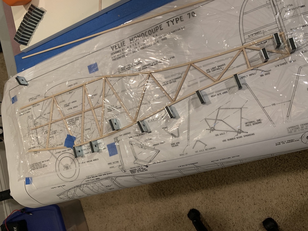
I was not familiar with this type of fuselage structure and building process. Every RC plane I've built so far has a simple box fuselage built with flat balsa sheet sides over formers, with more sheets covering the top and bottom. The Chicken Hawk was only a slight deviation from this method. I typically start by building the wings, but this time I went for the fuselage first. It will help put the challenging piece behind me much sooner and perhaps also help with figuring out CG and balancing; something I can do with a complete fuselage and tail section in place. I'm not sure about that but it seems like a reasonable expectation. Learning an important lesson from building the Chicken Hawk, I carefully read the building article and building log on RC Groups. My plan is to follow the more experienced builders' methods and adapts I progress. This is the first side structure that was built on top of the plans. Wax paper separates the structure from the plan and clear plastic w...